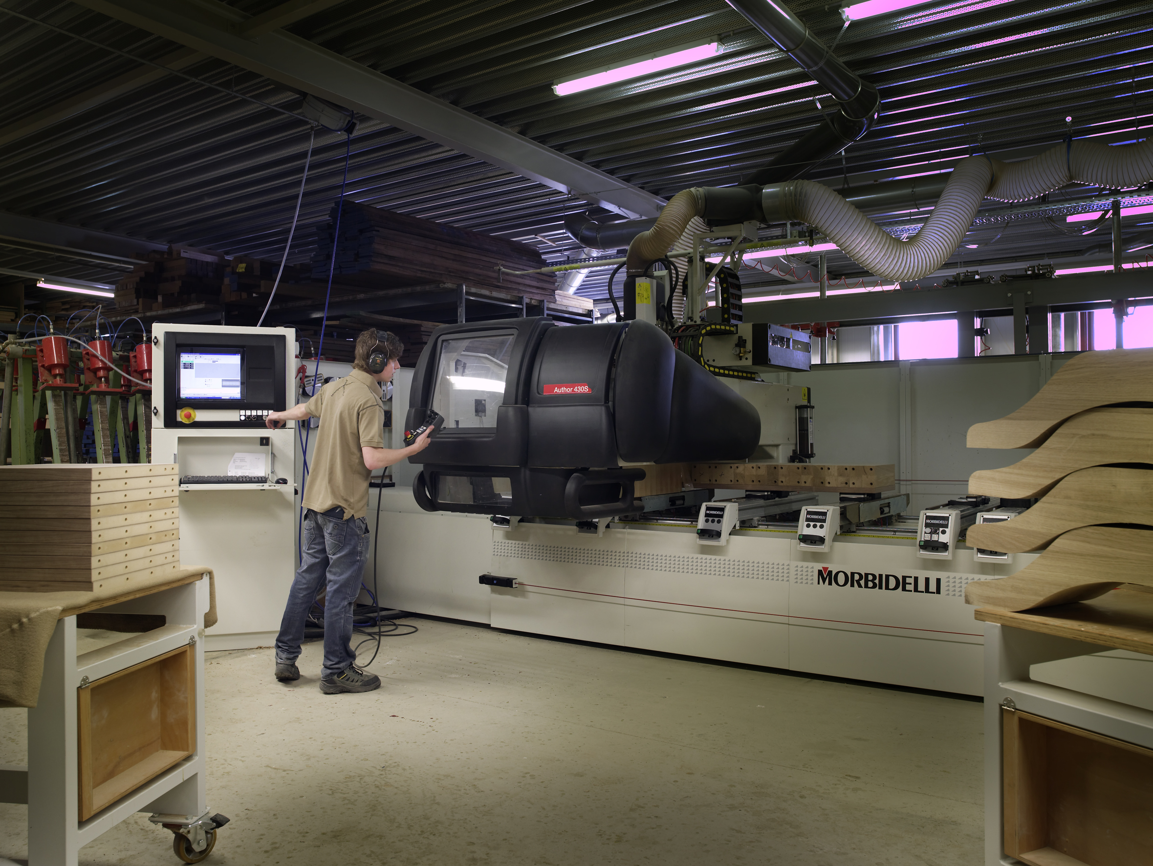
How to Stabilize High-Speed Finishing with Micro CBN Milling Tools
High-speed finishing is unforgiving. If the setup is solid, micro CBN tools can deliver consistent surface quality and tight size control. If the setup is loose, the machine will tell you quickly – usually by singing, marking the surface, or drifting a dimension while everyone pretends the feed chart is the problem.
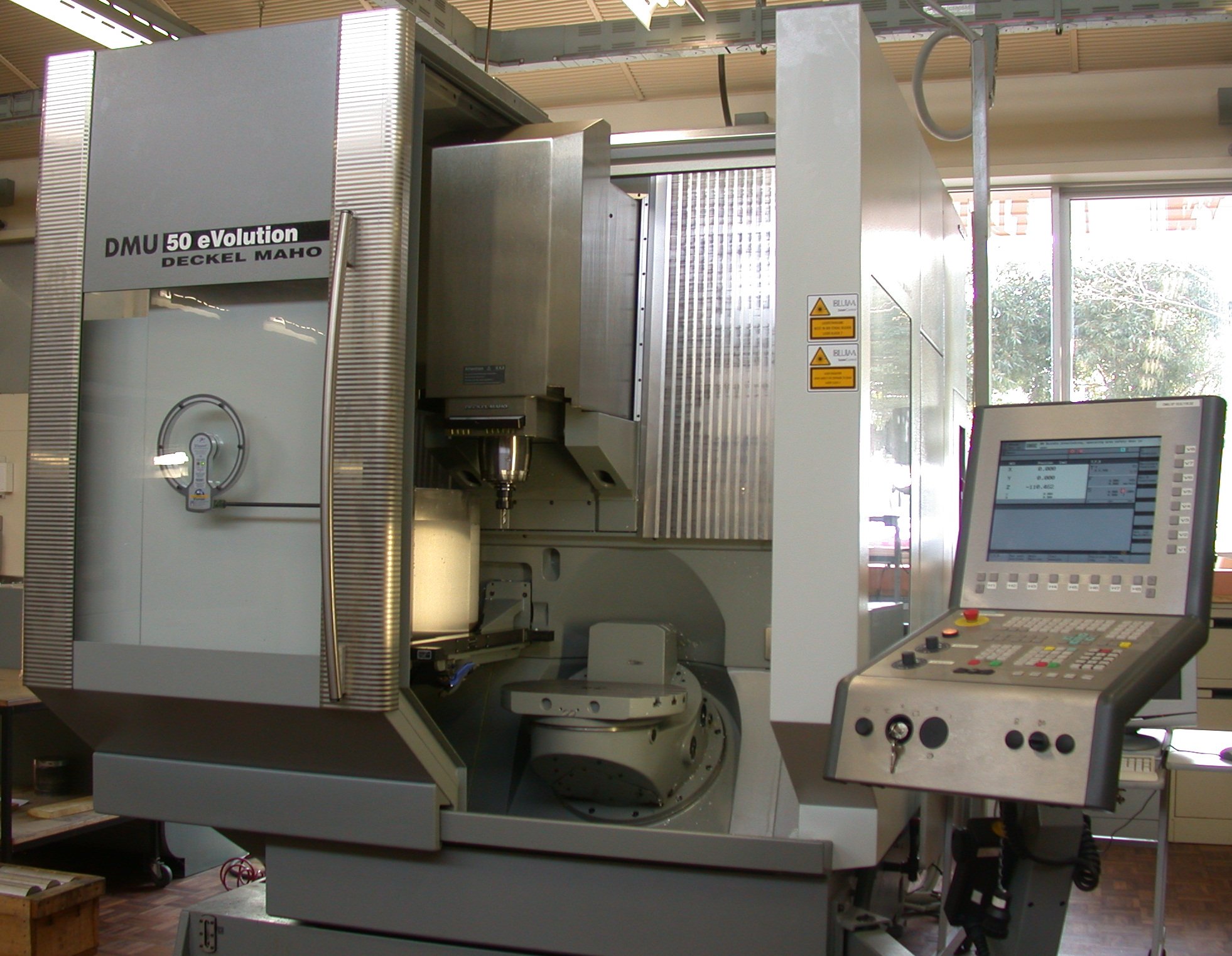
In this guide, we use micro CBN milling tools as the shorthand for small-diameter, precision finishing tools used on hard or difficult-to-finish materials. CBN means cubic boron nitride, a very hard cutting material chosen for wear resistance in demanding finishing work. The basic problem is not mysterious: finish quality depends on keeping the tool, spindle, workpiece, and process in a narrow band of stability.
If you want a broader background on finishing workflows, start with the homepage, then look at the related milling technology area, downloads, and news pages. For company context, see About and Contact.
Why micro CBN finishing is used for demanding surface-quality jobs
Micro CBN finishing is used when the process needs more than “good enough.” Typical uses include hardened steel components, precision molds, fine finishing passes on complex geometries, and parts where surface integrity matters as much as nominal size. The value is not hype; it is control. A good finishing tool removes small amounts of material cleanly, with less burr formation and better repeatability than a roughing-minded setup pretending to be a finishing strategy.
- Surface quality: fine toolpaths and stable cutting reduce visible marks.
- Tool life: the right geometry and stable engagement reduce premature wear.
- Repeatability: consistent setup reduces the “first part good, tenth part weird” pattern.
For general background on chatter and vibration behavior, Seco’s technical guidance on reducing chatter for better machining is a useful reference point. Kennametal’s note on reducing chatter and vibration in end milling reaches the same conclusion from a different angle: the process is usually won or lost before the first chip breaks.
The most common causes of chatter, poor finish, and size variation
Chatter is self-excited vibration during cutting. In plain language, the tool and machine start feeding each other bad ideas until the surface looks like it went through a slow earthquake. Poor finish and size variation often come from the same root causes:
- Excessive tool overhang or a slender setup that flexes under load.
- Runout that makes one cutting edge do more work than the others.
- Weak spindle or holder condition that adds vibration before cutting begins.
- Cutting data mismatch – speed, feed, and engagement that do not suit the geometry.
- Thin walls or poor part rigidity that let the workpiece move away from the tool.
- Chip packing and heat that distort the finish or push the tool off line.
Seco’s recent chatter and vibration guidance highlights the same failure modes: slender tools, thin-walled workpieces, wrong geometry, poor strategies, and runout all contribute to unstable finishing. The key point is practical: if the setup is not rigid, the cutting edge has to compensate for every weakness in the stack.
Toolholding, runout, and spindle-condition checks before cutting
Before adjusting feeds or blaming the insert, check the hardware. Micro tools magnify small errors. A holder that looks acceptable on a roughing job can be a problem in finishing because the tolerances are tighter and the engagement is lighter.
- Check holder cleanliness: wipe taper surfaces, collet bores, and shanks before assembly.
- Measure runout: indicate at the tool tip and confirm whether the actual eccentricity is within the process limit.
- Inspect the spindle nose and taper: damage, contamination, or wear can show up as finish marks long before a catastrophic failure.
- Verify clamping torque and stickout: too much stickout is a classic way to create a vibration problem and then call it a “parameter issue.”
A simple real-world check: if you see alternating bright and dull marks along a finished wall, the tool may be cutting unevenly because of runout or holder instability. If the finish gets worse as the tool extends farther from the holder, start with the setup, not the spreadsheet.
Cutting data and engagement choices that stabilize finishing passes
There is no universal feed-and-speed table that rescues a shaky setup. The point of cutting data is to match the process to the machine, material, tool geometry, and rigidity. For finishing, stability usually improves when the tool is not forced to take too much bite at once and the engagement is kept predictable.
- Use conservative engagement for finishing: small radial or axial cuts are easier to control than aggressive passes.
- Keep chip load consistent: uneven loading drives chatter and leaves a striped finish.
- Respect geometry: a micro CBN tool with a specific edge preparation will not behave like a general-purpose end mill.
- Change one variable at a time: if you alter speed, feed, and engagement together, you learn very little and waste a lot of good parts.
Manufacturers generally advise controlling cutting forces and matching the strategy to the tool’s stiffness. That is not flashy advice, but it is real advice. High-speed finishing succeeds when the tool stays in its stable window, not when it is asked to perform interpretive dance at the edge of its load range.
Workholding and part rigidity: what changes when walls get thin
Thin-walled parts are where stable finishing becomes a structural problem. The tool may be fine, but the part itself deflects under load. Once that happens, the surface finish and final size start following the part’s spring behavior rather than the drawing.
To improve rigidity:
- Support the part closer to the cut: reduce unsupported spans whenever possible.
- Distribute clamping force: avoid point loads that distort thin sections.
- Use sacrificial support or dedicated fixtures: when the part is delicate, the fixture should carry more of the fight.
- Sequence the cuts intelligently: roughing, semi-finishing, and final finishing should leave the part in a stable state for the last pass.
If the part moves when you tap it lightly or the same wall measures differently at different stages of the cycle, the problem may be clamping, not cutting. A stable setup keeps the part where the control expects it to be.
Coolant, chip evacuation, and heat control for consistent results
Heat is an underrated nuisance in finishing. It changes dimensions, softens the conversation between tool and material, and can make a good setup look inconsistent. Coolant and chip evacuation are not just for cleanliness; they help the tool cut the part you think it is cutting.
- Use coolant consistently when the process calls for it: interruptions in coolant can change the finish pattern.
- Clear chips away from the cut: recutting chips bruises the surface and loads the edge.
- Watch heat soak: long cycles can move dimensions even when the toolpath is unchanged.
- Check air blast or through-tool delivery: effective chip evacuation is often the difference between repeatable finish and random roughness.
When the finish degrades after a few parts rather than immediately, temperature and chip control deserve a close look. Finishing is picky about the environment. That is not a defect; it is the price of precision.
A quick troubleshooting checklist for setup verification
Use this before a finishing run or when the results start drifting:
- Confirm the holder, collet, and spindle interfaces are clean and properly seated.
- Measure tool runout and compare it with the job’s tolerance for finish stability.
- Check tool overhang and shorten it if the cut allows.
- Verify that the workholding supports the part near the finishing zone.
- Review speed, feed, and engagement for a conservative finishing pass.
- Inspect coolant delivery and chip evacuation at the actual cut point.
- Run a short test pass and inspect the surface before committing to full production.
One practical example: if a part comes off clean on the first setup but starts showing waviness after a tool change, do not jump straight to tool geometry. Recheck runout, holder fit, and stickout first. The hardware is often the shortest path to the answer.
When to test a different tool geometry or finishing strategy
If the basic checks are clean and the process still shows chatter, edge breakdown, or inconsistent finish, the geometry may simply be wrong for the job. That is not failure; that is process development doing its job.
Consider a different approach when you see:
- persistent chatter even after reducing stickout and cleaning up runout,
- finish quality that changes sharply with small parameter shifts,
- edge wear that appears too fast for the material and duty cycle,
- thin-wall distortion that cannot be controlled with the current strategy.
At that point, test a different edge prep, flute count, helix, or finishing strategy. In some cases, a lighter engagement, a different toolholder, or a revised toolpath will do more than another round of parameter guessing. The machine does not care about optimism; it cares about stiffness, geometry, and control.
Next step: make the setup easier to trust
High-speed finishing with micro CBN tools is a system problem, not a single-number problem. The fastest path to better results is usually a plain one: tighten the setup, verify runout, match the cut to the rigidity you actually have, and keep heat and chips under control. If you want to explore related technical resources, use the downloads section or contact the team for more guidance.
For deeper manufacturer references, see Seco’s article on vibrations in solid end milling and Kennametal’s note on machining finish quality and rigid toolholding principles. They reinforce the same idea from another angle: stability is built, not wished into existence.