
Before the first cut, I want the boring facts on paper. Everything else is theater with coolant on it.
When I stand in front of a fresh micro CBN finishing setup, I am not asking one question. I am asking a bundle of small ones: Is the part actually located the way the drawing says it should be? Is the tool healthy, or merely installed? Does the spindle know the difference between a stable setup and a hopeful one? Have we defined what “good” means before the chips start flying?
That sounds obvious because it is. Yet the first-cut failure is usually not dramatic. It is a slow collapse of assumptions. NIST manufacturing guidance keeps making the same unglamorous point: process control beats guesswork. Mitutoyo’s surface roughness material is a reminder that measurement only helps when the method is consistent. And Sandvik Coromant’s milling troubleshooting notes keep circling the same suspects: runout, clamping, wear, vibration, and chips that refuse to leave on their own.
If you have ever watched a demo part look perfect and then watched production turn into a negotiation, this article is for you. I will show you what to verify in the 30 minutes before the first cut, what to record so the setup can be repeated, and what early warning signs mean “stop and re-check” instead of “push through and hope.” When a team needs to turn that kind of checklist into a shared workflow, AI consulting services is one example of a planning resource for structuring the handoff from notes to repeatable process. If you want the broader site context, the Messen & Events page is the clean entry point, while the blog index, services page, downloads page, contact page, and homepage cover the rest of the path.
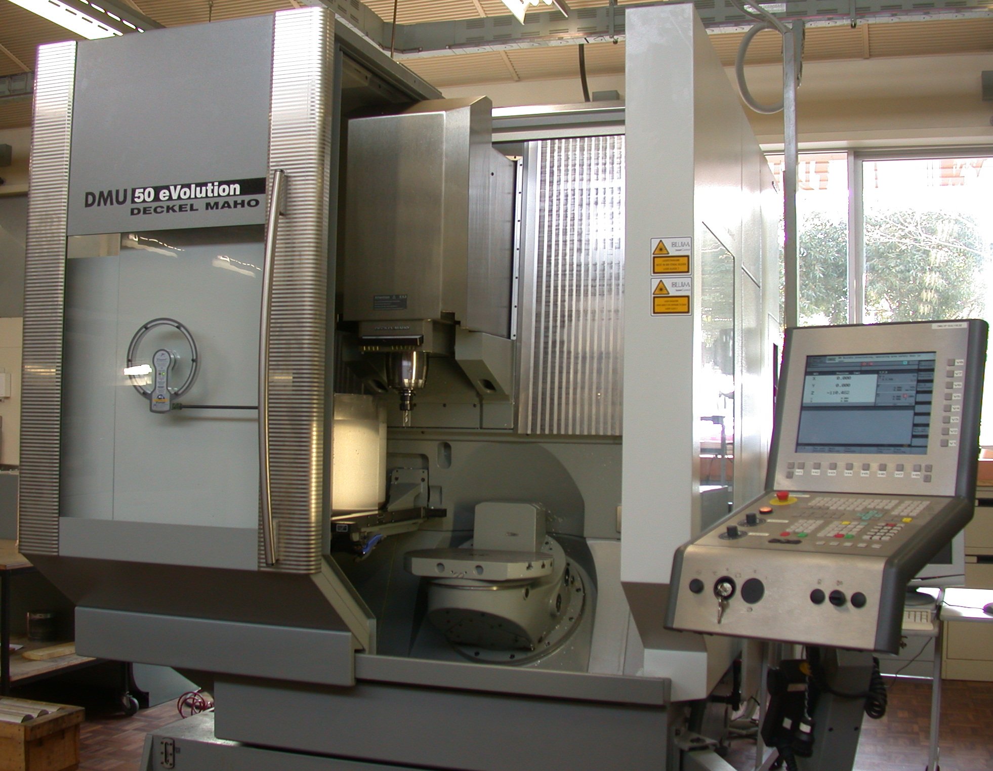
Why demos fail to translate into production
Demos fail for the same reason polished photographs fail to tell the whole story: they remove friction. The booth version of a micro CBN finishing process usually has the best fixture, the best operator, the cleanest tool, the friendliest material condition, and exactly the right amount of attention. Production gets none of that protection.
The most common first-cut gaps are boring, which is why people miss them:
- Setup gaps: the part is not located from the right datum, or the clamp force is not repeatable.
- Measurement gaps: the finish looks good, but nobody has agreed on where or how to measure it.
- Tool readiness gaps: the tool is installed, but edge condition, offset, or runout were never sanity-checked.
- Process assumption gaps: the demo used a speed, feed, coolant, or tool path that no one can reproduce later.
That is why I do not start with the spindle. I start with the question that usually gets people annoyed: what exact condition must be true for the first cut to count as valid? If the answer is vague, the first cut is already compromised.
One more useful rule: if the result can only be described as “looks fine,” it is not ready for production discussion. Roughness, edge condition, datum integrity, and tool behavior need a method, not mood. That is not me being difficult. That is just how evidence works.
For a plain-language reminder of why traceable measurement matters, the Mitutoyo roughness guide is useful. For why vibration and runout keep stealing clean finishes, Sandvik Coromant’s vibration guidance stays annoyingly on target.
A quick map of the terms
I like to define the vocabulary before anyone starts using shorthand as camouflage. The same word can mean three different things in a shop and cause three different kinds of trouble.
| Term | Plain meaning | Why I care |
|---|---|---|
| Micro CBN | A small cubic boron nitride cutting tool used for demanding finishing work where wear control and edge quality matter. | Tool condition and rigidity often decide whether the result is repeatable. |
| Datum | The reference point or surface the part is located from. | If the datum is wrong, the rest of the setup can be perfect and still miss the target. |
| Runout | How much the tool tip or holder deviates from perfect rotation. | Small runout errors often become visible finish errors. |
| Offset | The machine’s stored adjustment for where the tool actually reaches. | If the offset is wrong, the first cut teaches you the wrong lesson very quickly. |
| Chip evacuation | How effectively chips leave the cut instead of packing, recutting, or smearing. | Poor chip control changes heat, load, finish, and sometimes the mood in the room. |
| Repeatability | How closely the setup produces the same result more than once. | A setup that works once is a demo. A setup that works twice starts to matter. |
The 30-minute pre-run checklist
This is the part I would print and keep on the machine. Not for decoration. For when people start trusting the sound of the spindle more than the facts.
| Minute range | What I check | What “pass” looks like | What makes me stop |
|---|---|---|---|
| 0-5 | Part and fixture | Datum, clamp, and access are clear | Part location is ambiguous or unstable |
| 5-10 | Tool and spindle | Tool is verified and runout is sane | Tool edge, holder, or offset is in doubt |
| 10-15 | Process inputs | Speed, feed, coolant, and path intent are written down | No one can explain the chosen window |
| 15-20 | Workholding and chip control | Clearance and chip flow make sense | Chips will obviously pack or recut |
| 20-25 | Measurement readiness | First measurement point and record sheet are ready | Inspection method is still being negotiated |
| 25-30 | Safety and repeatability | Guards, interlocks, and restart rules are clear | People are improvising around moving hardware |
That is the whole trick. I am not trying to make the first cut clever. I am trying to make it repeatable. Clever is how a booth demo wins applause. Repeatable is how a production run survives contact with reality.
1) Part and fixture: datum plan, clamping stability, measurement access
The part comes first because the part decides what the process is allowed to be. If the datum is wrong, the clamp is weak, or the measurement access is awkward, the rest of the checklist is just machine poetry.
I check three things immediately:
- Datum plan: which surface, hole, shoulder, or edge establishes the location.
- Clamping stability: whether the part can be loaded, unloaded, and reloaded without wandering.
- Measurement access: whether the inspection tool can reach the first critical surface without disassembly gymnastics.
Example one: if the part is seated against a datum face that is scratched, contaminated, or inconsistent between loads, the finish result may look fine while the dimension slowly drifts. That is not a finishing problem. That is a location problem pretending to be a cutting problem.
Example two: if the first measurement point is hidden under the fixture, the team will either skip the measurement or invent one that is easier to reach. Both outcomes are worse than planning access before the run.
I also want one simple sentence written down before the spindle starts: “This is the reference setup we are comparing against.” Without that sentence, every later adjustment becomes a fresh debate.
Practical checks for this section:
- Confirm the part revision and material condition.
- Verify the datum surfaces are clean and undamaged.
- Check clamp force, jaw contact, or fixture support points.
- Dry-fit the part once if the process allows it.
- Make sure the first measurement can be taken without changing the setup.
2) Tool and spindle: condition, runout, offsets, and tool length references
The tool is where a lot of optimistic setups go to die. People assume that because the holder is tight and the tool is mounted, everything else will politely cooperate. That assumption is expensive.
For the tool, I want four checks:
- Tool condition: inspect the edge, shank, and holder for chips, wear, damage, or contamination.
- Runout sanity check: confirm the tool is not wobbling itself into a bad finish.
- Length reference: verify the correct tool length or gauge reference is in the machine.
- Offset verification: make sure the machine’s stored offset matches the actual setup, not the memory of one tired afternoon.
Runout matters because tiny deviations at the tool tip show up as visible variation on the surface. That is why I do not skip the basic holder check. Sandvik Coromant’s troubleshooting guidance keeps pointing back to the same mechanism: tool wear, clamping, and vibration are not background noise, they are the actual problem most of the time.
If the tool is fresh but the finish still looks ragged, I want to know whether the holder is clean, whether the edge is actually the one you think it is, and whether the machine has the right reference loaded. People love blaming the cutter because it is visually convenient. Convenient is not correct.
What I record before the run:
- Tool ID and holder ID.
- Edge condition and any visible wear.
- Gauge length or stickout.
- Offset and reference method.
- Any tool-change or inspection interval for the first run.
If I cannot write those down in under two minutes, the setup is still too foggy for a first cut.
3) Process inputs: speed, feed, coolant or air, and path expectations
After the part and tool are sane, I check the process inputs. Not because machine settings are the most important thing, but because they are the easiest thing to get wrong while everyone is smiling at the monitor.
The minimum process sheet should answer these questions:
- What speed range are we using, and why this range instead of a guess?
- What feed range are we using, and what would tell us it is too aggressive or too conservative?
- Are we using coolant, air, mist, or a mixed strategy, and where does it actually hit the cut?
- What is the tool path supposed to do at entry, during the finish pass, and at exit?
I like to make the programmer say the process back to me in plain language. If that sounds childish, fine. It works. If the explanation gets vague around the entry or exit move, there is usually a hidden assumption in the path. Hidden assumptions are why the first cut starts on schedule and ends in confusion.
Example: if the demo relied on a directed air stream to clear chips, I want to know whether that air is part of the process or part of the stage show. If the finish only stays clean when chip evacuation is perfect, then chip evacuation is not a side note. It is the process.
Another useful check is to write down the actual expected tool path behavior: single pass, multiple passes, dwell, compensation, or any special lead-in/lead-out move. If the answer is “the CAM already handles that,” I still want the human explanation. Software is not a substitute for process intent.
Quick record list:
- Spindle speed and feed target.
- Coolant or air strategy.
- Pass count and path logic.
- Entry/exit behavior.
- Any parameter that the process is unusually sensitive to.
4) Workholding and chip control: clearance, evacuation, and first-second behavior
Workholding and chip control belong together because they usually fail together. A fixture can be mechanically fine and still lose the battle once chips start accumulating where they should not.
I check for three things:
- Clearance: does the tool have room to finish without scraping the fixture or crowding the part?
- Chip evacuation: do chips leave the cut, or do they collect and smear?
- First-second behavior: what happens in the first few seconds of cutting, before anyone starts telling stories about the result?
If the process depends on a very specific air blast or coolant angle, I write that down as a required condition. Otherwise it becomes one of those convenient details that everyone forgets until the first production run goes sideways.
This is also where vibration shows itself. If the tool path sounds clean for three seconds and then starts to sing like a bad bearing, I do not keep cutting just to be polite. I stop, check the boring thing, and make the fixture and chip path prove themselves again. Sandvik Coromant’s vibration guidance is useful because it connects the sound of the cut to the actual mechanical problem instead of pretending the machine is being dramatic for attention.
Here is the part nobody likes to admit: the first few seconds of the cut are often enough to reveal whether the setup is honest. If chips pack immediately, if the surface flashes unevenly, or if the process sounds harsher than expected, the setup may be wrong. There is no prize for ignoring that and waiting for the part to become “less wrong.”
Practical checks:
- Verify chip escape paths around the tool and part.
- Look for pinch points or rub points in the fixture.
- Confirm the coolant or air path is not blocked.
- Check whether the tool has enough clearance throughout the finish path.
- Agree in advance on what sound, chip form, or surface change means “stop.”

5) Measurement readiness: what to measure first and how to record it
This is where demos often get lazy. Everyone looks at the part, nods a little too hard, and then says something about “feel.” Feel is not a method. It is a mood with a clipboard.
The first measurement should answer one question: did the setup produce the intended surface or edge condition where it matters most? For most micro CBN finishing work, that means I check the surface that carries function first, then the edge condition, then any dimension that is known to drift when the process is unstable.
I like to define the first measurement sequence like this:
- Measure the primary surface or geometry that matters to function.
- Check the edge or burr condition where handling or assembly could be affected.
- Record the method, location, and instrument used.
- Repeat the same check on the next part before changing anything.
That sequence keeps the team from measuring whatever is easiest and calling it validation. The easiest point is often not the important one. Engineering is rude that way.
The measurement record should include:
- instrument name and type,
- measurement location,
- part number and revision,
- who measured it,
- when it was measured,
- what the pass/fail rule was, and
- whether the same result can be repeated on the next part.
If you want a reason to care about that level of detail, the Mitutoyo surface roughness guidance is the simple answer: measurement is only useful when the method is clear enough to repeat.
A tiny but important habit: write down the result while the part is still on the bench. A memory note made after the next meeting is not a measurement record. It is fan fiction.
6) Safety and repeatability: guards, interlocks, and restart conditions
Safety is not the polite section at the end. It belongs in the same breath as repeatability, because a process that cannot be restarted safely is not really ready. A process that cannot be paused safely is even worse.
Before the first cut, I want these basics clear:
- Are guards and interlocks active and functioning?
- Does everyone know who is allowed to restart the cycle?
- What is the safe path for loading, unloading, and checking the part?
- What conditions force a stop: chip packing, unusual sound, unexpected surface change, or a measurement miss?
Repeatability needs the same discipline. If the first cut requires a secret handshake, the process is fragile. If the second setup needs a “small tweak” that nobody writes down, the process is already drifting into folklore.
I also like to do a dry restart check. Not a cut. Just a check. If the team cannot describe the restart sequence without looking at each other, the machine should stay idle until that changes. That is not caution for its own sake. That is avoiding a predictable mistake.
Quick repeatability test:
- Repeat the clamping sequence once before cutting.
- Confirm the tool and offsets again after the dry run.
- Verify the measurement point is the same on each part.
- Record who is responsible for any change.
Mini first-cut observation guide
Here is what I watch in the first cut, before anyone starts over-interpreting the result.
Sound
A stable cut usually has a consistent sound. A sharp change in tone, a rattle, or a chatter pattern usually means the setup has found a weak spot. I do not wait for that to become a full performance.
Chips
Chips should leave cleanly and predictably. If they pack, smear, or collect in a way that changes the cut, the process may need a different evacuation path or a change in parameters.
Surface behavior
Look for streaks, uneven sheen, edge pullout, burr growth, or visible transition marks. Do not confuse a single shiny pass with a stable finish. The part after the first part is usually the honest one.
When I stop
- If the sound changes unexpectedly.
- If the chips stop leaving the cut cleanly.
- If the first measurement is already outside the agreed window.
- If the surface or edge condition changes in a way nobody can explain.
When I restart
I restart only after the cause is checked, written down, and corrected in one variable at a time. If three things change at once, you have learned almost nothing except how people can argue very quickly.
Close
The point of this 30-minute checklist is not to slow you down. It is to stop the usual lie that a clean demo automatically becomes a clean production run. It does not. A real setup has to survive datum checks, runout checks, process inputs, chip flow, measurement, safety, and the ugly fact that the second part matters more than the first.
My short version is simple: measure the boring things before the spindle teaches you the hard way. If the datum is right, the tool is verified, the process inputs are written down, the chips clear, the measurement method is set, and the restart rules are clear, you have something worth testing.
If you want the next step, keep the context together. The blog index is where related notes live, the downloads page is the obvious place to keep supporting material, and the contact page is where a follow-up belongs when the checklist turns into a real trial. If you need the trade-fair frame again, the Messen & Events page is the cleanest way back. The services page and homepage fill in the rest when you need a broader orientation.
Key points to keep:
- Check the part and fixture before you trust the tool.
- Verify tool condition, runout, and offsets instead of assuming them.
- Write down speed, feed, coolant, and path intent before the cut.
- Confirm chip flow and first-second behavior, not just the final part.
- Measure the first critical surface with a repeatable method.
- Stop quickly when the sound, chips, or surface stop matching the plan.
That is enough to keep the first cut honest. The rest is just the machine doing what you asked, which is the sort of favor it is much better at when the checklist is not lying to it.
