
Micro CBN finishing works when the whole system behaves, not when one part of the setup looks impressive in isolation. If the surface is not where you want it, the first suspect is not always the tool. Often it is the machine, the fixture, the chip flow, or the way the test was run.
Readers usually come to this topic with the same questions: What does “high speed finishing” really mean? Why does one micro CBN setup leave a clean surface while another leaves a short, expensive lesson? Which variables matter first, and which ones can wait? The answer is practical, not mystical. High-speed finishing is a controlled process, and controlled processes have dependencies.
This guide explains those dependencies in plain English so you can ask better questions, structure cleaner trials, and avoid the classic trap of blaming the cutting edge for a problem that started somewhere else. If you want the broader site context, start at the home page, or jump to services if you are looking for practical machining support. If you are comparing these questions with exhibition planning, the CIMES page gives that part of the site a place in the conversation.
For a broader technical backdrop, it helps to keep one eye on the machine side of the story. Sandvik Coromant’s overview of high-speed machining is a useful reminder that speed alone is not the achievement. Stability is. For the measurement side, the surface roughness reference is a useful way to separate what looks clean from what actually measures clean.
What you will get from this article:
- A clear definition of high-speed finishing and what it is trying to control.
- A realistic view of what micro CBN tools can do, and what they cannot fix.
- A machine capability checklist you can use before a trial starts.
- A simple method for testing one variable at a time without turning the trial into a lab accident.
- The key measurements that actually tell you whether the finish is improving.
Contents
- 1. What high-speed finishing is trying to achieve
- 2. Micro CBN tools: strengths and limits
- 3. Machine capability: the part people underestimate
- 4. Workholding and runout: where consistency starts
- 5. Cutting environment: coolant, air, and chip control
- 6. Process window thinking: how to run a small test
- 7. How to verify results without fooling yourself
- 8. Common misconceptions that keep failing teams busy
- 9. FAQ
1. What high-speed finishing is trying to achieve
High-speed finishing is not just “cut faster.” It is the use of a controlled cutting strategy to produce a better final surface, with stable edge quality and predictable cycle behavior. In practice, that means three things matter at the same time: the finish on the part, the repeatability from part to part, and the ability to hold that result without constant manual rescue.
A useful working definition is this: if the process looks fast but the outcome varies, it is not a finishing process yet. It is a gamble with a spindle.
| Goal | What it means in practice | What usually spoils it |
|---|---|---|
| Surface quality | Low roughness, consistent texture, clean directionality | Runout, chatter, recutting, unstable chip evacuation |
| Edge quality | Controlled corners, limited burrs, no torn edges | Wrong tool geometry, poor support, vibration |
| Throughput | Less touch time without sacrificing quality | Overly conservative setup, unstable machine behavior, repeated rework |
If you want the terminology in one place, the CBN in micro CBN stands for cubic boron nitride. It is one of the hardest cutting-material families used in machining, and it is often selected when abrasive or hardened materials make ordinary tooling give up early. A concise reference is the cubic boron nitride overview.
For readers who want to anchor the finish side of the problem, the surface roughness reference is a plain-language way to separate “looks better” from “measures better.” Those are not the same thing. Shops discover this at some cost, which is how most standards are born.
Quick definitions
| Term | Simple definition | Why it matters |
|---|---|---|
| Micro CBN tool | A small-form cutting tool using cubic boron nitride cutting edges | Designed for fine finishing, not for compensating for a sloppy setup |
| Runout | How far the rotating tool or workpiece deviates from perfect center | Raises one cutting edge, lowers another, and quietly ruins consistency |
| Chatter | Self-excited vibration during cutting | Marks the surface, reduces tool life, and wastes confidence |
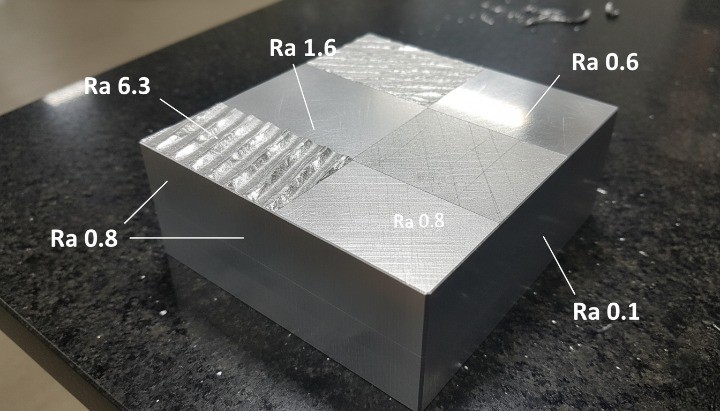
| Ra | A common average roughness metric | Useful for comparing finish trends if the measuring method stays constant |
| Process window | The range of settings where the cut remains stable and acceptable | Shows whether the process is robust or just lucky today |
2. Micro CBN tools: strengths and limits
Micro CBN tools are designed to do fine finishing work on difficult materials. That usually means small stepovers, controlled engagement, predictable edge behavior, and a surface that can pass inspection without hand-polishing the evidence away.
What these tools are not designed to do is compensate for a weak machine, a shifting fixture, or a coolant strategy that seems optimistic. Tooling is important, but it is one part of a chain. A strong link is useful. It is not a replacement for the chain.
Common misconceptions show up here first:
- “A harder tool solves a soft setup.” No. Hardness does not fix instability.
- “Smaller must mean safer.” Not necessarily. A micro tool can be more sensitive to runout and chip packing.
- “If it cut once, the process is proven.” One good part is not a process window.
- “The finish problem is only on the cutting edge.” Often the real culprit is before the edge ever sees material.
Micro tooling also narrows the margin for error on tool stickout, clamping quality, and wear progression. That makes it valuable for finishing and unforgiving for casual setup habits. A shop can get away with casual habits for a while. Then the finish report arrives.
One practical way to think about tooling selection is to ask three questions:
- What material and geometry is the tool meant to finish?
- What surface result is expected, and how will it be measured?
- What machine and fixture behavior does the tool assume is already under control?
Tooling selection lens
| Decision point | What to check | Why it matters |
|---|---|---|
| Cutting edge geometry | Edge preparation, corner radius, rake concept | Affects cutting forces and surface consistency |
| Tool diameter and stickout | Shortest practical overhang | Reduces deflection and vibration |
| Work material | Hardness, abrasiveness, thermal behavior | Determines wear rate and chip formation |
| Coolant compatibility | Flood, mist, air blast, or through-tool delivery | Affects heat, chip evacuation, and finish stability |
3. Machine capability: the part people underestimate
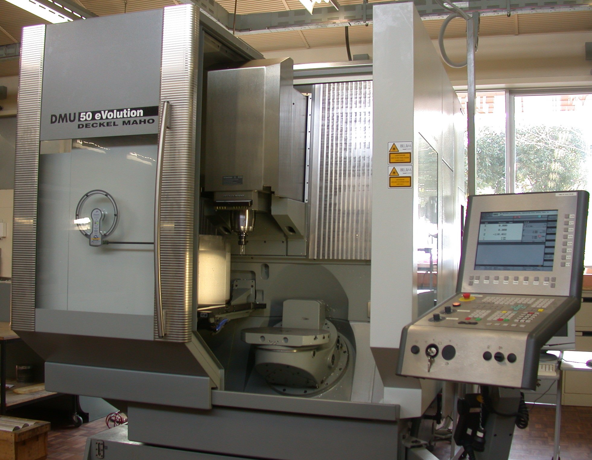
Micro CBN finishing is often sold as a tooling question because tooling is easy to photograph. Machine behavior is less glamorous and far more important. High-speed finishing asks the machine to stay stable while moving quickly, changing direction cleanly, and resisting vibration across a narrow operating band.
The machine side of the equation includes spindle stability, acceleration, jerk behavior, dynamic stiffness, speed range, and sensitivity to resonance. If those terms sound abstract, translate them this way: the tool can only finish the surface that the machine is willing to present to it.

A good reference for the machine-side logic is the same high-speed machining discussion from Sandvik Coromant linked above. It is a reminder that speed without stability is just a louder way to lose quality.
Machine capability checklist
| Capability | What “good enough” looks like | What to watch for |
|---|---|---|
| Spindle stability | Low vibration at the intended operating range | Finish changes as speed changes |
| Acceleration and jerk | Smooth transitions into and out of the cut | Marks at corners, poor entry/exit consistency |
| Speed range | Usable operating band that matches the tool and material | Forcing the process into a bad speed because the machine can get there |
| Thermal behavior | Repeatable behavior after warm-up | One cold part, one hot part, and two different stories |
| Vibration sensitivity | Stable finish across the intended tool overhang | One setup length works, the next one sings |
A practical rule: if the machine needs constant heroics to make the surface acceptable, the process is not ready. That does not mean the machine is bad. It means the process still needs constraints.
4. Workholding and runout: where consistency starts
Runout is one of those small words that causes large bills. It means the rotating tool or workpiece is not centered perfectly, so one side of the cut works harder than the other. In finishing, that uneven load shows up quickly in the surface and at the edge.
Good workholding is not just “clamp the part harder.” It is repeatability. The part should locate the same way every time, remain stable during the cut, and release without introducing distortion that changes the next setup. If the fixture changes the part shape, the inspection data is already compromised.
Three practical checks help here:
- Locate on stable datums. Use the same reference surfaces every time.
- Minimize overhang. Shorter stickout means less deflection and less drama.
- Measure runout early. Do not wait until the surface proves you were optimistic.
The inspection logic in this section connects directly to the page on contact if you need a second set of eyes on the setup, or to the blog if you want more process notes like this one.
Workholding stability checklist
| Item | Question to ask | Typical failure mode |
|---|---|---|
| Fixture repeatability | Does the part return to the same location after reloading? | Surface changes between parts for no obvious reason |
| Clamping strategy | Is the part secure without bending into a new shape? | Hidden distortion that appears as waviness |
| Tool interface | Is the tool holder and spindle interface clean and consistent? | Built-in runout and unstable tool presentation |
| Inspection datum | Are measurements taken from the same reference point? | Comparing different parts of the part as if they are the same surface |
5. Cutting environment: coolant, air, and chip control
Once the tool and machine are behaving, the cutting environment decides whether the finish survives contact with reality. Chips need to leave the cut cleanly. Heat needs to be managed. Recutting needs to be prevented. These are not decorative concerns. They are the difference between a finish and a smear.
Depending on the material and geometry, the right strategy may be flood coolant, directed air, through-tool delivery, or a combination. The wrong strategy is usually the one that makes the operator say, “It looked fine from a distance.” That is rarely a compliment in machining.
Environment factors that matter
- Coolant direction: Aim it where chips actually form, not where the machine brochure placed the nozzle for symmetry.
- Chip evacuation: Verify that chips leave the engagement zone before the next pass arrives.
- Temperature control: Keep the process from drifting as the part and tool warm up.
- Recut prevention: Avoid chips crossing the surface again and again like they are reviewing the work.
A common failure scenario looks like this: the first few passes produce a promising finish, then the later parts dull, smear, or show random marks. In many cases the tool did not suddenly become poor. The environment changed. Chips accumulated, coolant coverage shifted, or heat built up enough to move the process out of its narrow window.
If your team wants to keep trials organized, this is where a simple tracking system helps. Some shops use a work order management software builder to keep setup notes, parameter changes, and inspection results in one place instead of scattered across notebooks and phone photos. The software is not the process. It just keeps the process from hiding under a pile of screenshots.
6. Process window thinking: how to run a small test
A process window is the range of settings where the finish remains acceptable. The point of testing is not to prove every possible setup. The point is to find out where the process is robust and where it is fragile.
That means the first trial should be small, controlled, and documented. Change one variable first. Keep the rest constant. If the result improves, you have learned something. If the result degrades, you have also learned something, which is more expensive but still useful.
What to change first
| Variable | Why test it early | Keep constant while testing |
|---|---|---|
| Cutting speed | Strong effect on surface and tool behavior | Tool geometry, fixture, measurement method |
| Feed rate | Affects load, finish texture, and burr formation | Tool stickout and coolant strategy |
| Axial or radial engagement | Changes chip load and thermal behavior | Same stock material and inspection point |
| Coolant or air strategy | Can move the process from stable to unstable fast | Same tool and same part geometry |
Use a simple trial log with columns for tool ID, part ID, setup date, machine, fixture, speed, feed, coolant strategy, inspection method, and result. That may sound like paperwork. It is. So is re-machining three parts because nobody wrote down what changed.
This is also the point where the article links back to the broader site strategy. Start from the about page if you want the company background, or use the blog to compare this guide with the other process notes. If you already know what you need and want a direct conversation, go to contact.
7. How to verify results without fooling yourself
The finish should be verified with a measurement plan, not with optimism. Surface quality, edge quality, and burr behavior all matter. If the inspection method changes from trial to trial, the data stops being data and starts being an opinion with a micrometer nearby.
Surface roughness metrics such as Ra are useful, but they are not the whole story. A part can look smooth and still fail on edge quality, burrs, or local defects. The inspection plan should match the part’s actual requirement, not the easiest number to report.
What to measure
| Measurement | What it tells you | Use it when |
|---|---|---|
| Ra | Average roughness trend | You need a common finish metric for comparison |
| Peak-to-valley or related roughness measures | Whether isolated peaks or valleys are still present | The surface must be more than “generally fine” |
| Edge quality | Whether edges stayed clean during the cut | Function depends on a sharp, controlled edge |
| Burr behavior | How much cleanup the part still needs | Secondary operations are costly or limited |
| Visual inspection under magnification | Local damage, tearing, re-cut marks, or chatter traces | You want to confirm what the numeric result really means |
Keep the measurement setup constant: same instrument, same location, same operator if possible, same part temperature, same method for reporting. If a part measures better only because the inspector changed location, that is not progress. That is a paperwork event.
For more on why surface roughness matters as a measurement category, see the surface roughness reference. It is a useful reminder that “finish” is not a single number, even if a sales sheet would prefer it to be.
8. Common misconceptions that keep failing teams busy
Most finishing problems survive because of assumptions. Here are the ones that appear often enough to deserve their own section.
| Assumption | Why it fails | Better approach |
|---|---|---|
| “The tool is the whole solution.” | The machine, fixture, and environment still shape the result | Validate the full chain before changing the edge geometry |
| “A great finish on one part proves the process.” | One part does not show drift, wear, or variation | Run a small repeatable sample and compare across parts |
| “Higher speed always means better finish.” | Speed can improve or destroy stability depending on the system | Find the stable speed band first |
| “Coolant is only about temperature.” | Chip control and recutting are often the real issue | Choose delivery based on chip evacuation as well as heat |
| “Measurement is a final step.” | Without a plan, you cannot tell what changed | Define the measurement method before the first cut |
The short version is this: quality finishing is a system property. If one part of the system is unplanned, the result becomes a negotiation between physics and hope. Physics tends to win.
9. FAQ
How many parts do you need for a first validation?
Enough to show repeatability, not just a lucky start. For a first pass, a small sample is usually better than a large, uncontrolled run. A practical baseline is to cut a few parts under identical conditions, inspect each one the same way, and look for stability rather than a single best result. If the first part is good and the next two drift, the process is not validated.
How do you compare two tool options fairly?
Use the same material batch, the same machine, the same fixture, the same stickout, the same program logic, and the same inspection method. Change only the tool option you want to compare. If several variables change at once, you are no longer comparing tools. You are comparing guesses.
Do you always need the highest spindle speed available?
No. You need the speed range that gives the most stable finish for the part, tool, and machine combination. The fastest setting that looks impressive on a screen is not automatically the best choice. Screens are very good at being enthusiastic.
What should a first-trial checklist include?
Tool geometry, stickout, workholding method, coolant or air strategy, target speed and feed, measurement method, and a note on what stays constant. If you also record part temperature and tool wear state, you will thank yourself later.
Conclusion
Micro CBN finishing succeeds when the full process behaves. That means the tool is appropriate, the machine is stable, the workholding is repeatable, the chip flow is controlled, and the inspection method is fixed before anyone starts celebrating.
If you want the shortest possible version of the lesson, it is this:
- Define the finish goal clearly.
- Validate the machine and fixture before blaming the tool.
- Control coolant, chip flow, and re-cutting.
- Change one variable at a time.
- Measure the result the same way every time.
If that is the level of control you need, the next step is straightforward: review the services page, scan the blog for related process notes, or go straight to contact with the part, material, and finish target you are trying to hold. A clean question is cheaper than a messy trial.
